ByJohn A
How a 15 kVA Single Phase Transformer Handles Electrical Loads
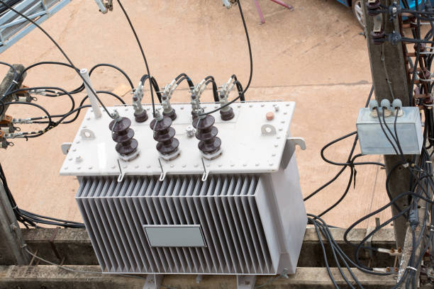
A 15 kVA single phase transformer is designed to transfer electrical energy between circuits while changing voltage levels to suit the requirements of connected equipment. It is commonly used in residential buildings, small commercial premises, workshops, control systems, and other installations where single-phase power distribution is appropriate. Understanding how this 15 kVA single phase transformer handles electrical loads helps users select suitable equipment, manage power demand, and maintain reliable electrical operation.
The transformer’s performance depends on several factors, including its rated capacity, input and output voltage, connected load, power factor, operating temperature, and installation conditions. Although a 15 kVA rating indicates its apparent power capacity, the actual amount of useful electrical power available to equipment depends on the characteristics of the load and the transformer’s operating limits.
This article explains how a 15 kVA single phase transformer works, distributes electrical power, responds to different loads, and maintains stable operation under normal operating conditions.
Understanding a 15 kVA Single Phase Transformer
A single-phase transformer is an electrical device that transfers energy between two circuits through electromagnetic induction. It typically consists of a primary winding, a secondary winding, and a magnetic core. These components work together to transfer alternating-current (AC) power from the input side to the output side.
The primary winding receives electrical energy from the supply. This current creates a changing magnetic field in the core, which induces a voltage in the secondary winding. The output voltage depends mainly on the ratio of turns in the primary and secondary windings.
A 15 kVA transformer has a rated apparent power capacity of 15 kilovolt-amperes. This rating indicates the maximum apparent load it is designed to handle under its specified operating conditions.
What Does the 15 kVA Rating Mean?
Kilovolt-amperes measure apparent power, which accounts for both real power and reactive power in an AC electrical system. The relationship between apparent power, voltage, and current is particularly useful when evaluating transformer capacity.
For a single-phase transformer, apparent power is calculated using the following formula:
[
S = \frac{V \times I}{1000}
]
Where:
- (S) is apparent power in kVA.
- (V) is voltage in volts.
- (I) is current in amperes.
For example, if a 15 kVA transformer supplies a 240 V single-phase load, its rated secondary current would be approximately:
[
I = \frac{15,000}{240} = 62.5\text{ A}
]
This means the transformer can supply approximately 62.5 A at 240 V when operating at its rated capacity and under the applicable design conditions.
The actual allowable current may be affected by ambient temperature, cooling, installation requirements, and manufacturer specifications. The transformer must also be protected against excessive current and other electrical faults.
How a 15 kVA Single Phase Transformer Handles Electrical Loads
A transformer handles electrical loads by transferring power from the primary winding to the secondary winding through a changing magnetic field. When equipment is connected to the secondary side, it draws current according to its electrical characteristics and operating requirements.
As the connected load changes, the secondary current changes as well. The primary winding responds by drawing the current needed to supply the load, while the magnetic core provides the coupling between the two windings.
1. Voltage Transformation
One of the main functions of a 15 kVA single phase transformer is to increase or decrease voltage.
A step-down transformer reduces a higher input voltage to a lower output voltage. For example, a transformer may reduce a distribution voltage to a level suitable for lighting, appliances, control equipment, or other electrical loads.
A step-up transformer performs the opposite function, increasing voltage where the application requires it.
The relationship between voltage and winding turns can be expressed as:
[
\frac{V_p}{V_s} \approx \frac{N_p}{N_s}
]
Here, (V_p) and (V_s) represent the primary and secondary voltages, while (N_p) and (N_s) represent the corresponding winding turns.
The actual voltage relationship is influenced by transformer design, winding resistance, leakage reactance, and the connected load.
2. Current Changes According to the Load
Voltage and current are closely related to the transformer’s winding ratio. For an ideal transformer, the voltage decreases as current capacity increases for the same transferred power, and vice versa.
When a load draws more current from the secondary winding, the primary side draws additional current to supply the required power, subject to losses and operating limits.
For example, a transformer supplying a small lighting circuit may draw relatively little current. When additional equipment is connected, the total current increases. If the combined demand approaches the transformer’s rated capacity, the installation must be monitored to ensure the transformer remains within its permitted operating limits.
3. Power Transfer Through Electromagnetic Induction
A transformer does not transfer electrical power through a direct conductive connection between its primary and secondary windings in a conventional isolated design. Instead, alternating current in the primary winding produces a changing magnetic flux in the core, inducing voltage in the secondary winding.
When a load is connected, current flows through the secondary circuit. The resulting electrical demand is reflected back to the primary supply through electromagnetic coupling.
This process allows a transformer to change voltage while maintaining an approximately corresponding relationship between input and output power, minus losses.
Understanding Different Types of Electrical Loads
A 15 kVA single phase transformer may supply several types of electrical loads. Each type affects current, power factor, voltage regulation, and operating temperature differently.
Resistive Loads
Resistive loads include many conventional heating elements and incandescent lighting systems. These loads convert electrical energy mainly into heat or light.
Their current is generally in phase with the applied voltage, giving them a power factor close to one under normal conditions. Consequently, their real power in kilowatts is approximately equal to their apparent power in kVA.
For example, a 10 kVA resistive load operating at a power factor of 1 requires approximately 10 kW of real power. This load would use two-thirds of a 15 kVA transformer’s rated apparent power, assuming suitable voltage, current, and operating conditions.
Inductive Loads
Inductive loads include motors, pumps, compressors, and certain types of electrical machinery. These devices use magnetic fields during operation and commonly draw reactive power.
As a result, their power factor may be lower than that of resistive loads. A transformer supplying inductive equipment must handle the apparent power associated with both real and reactive components.
Motors can also draw a high starting current when switched on. If several motors start simultaneously, the temporary current demand may cause voltage dips or place additional stress on the transformer.
Appropriate motor starting methods, load sequencing, and circuit protection can help manage these effects.
Electronic and Nonlinear Loads
Electronic equipment, including computers, variable-speed drives, and some power supplies, may draw current in a nonlinear manner. These loads can introduce harmonic currents into the electrical system.
Depending on their magnitude and frequency, harmonics can increase heating in transformer windings and the magnetic core. Where nonlinear loads represent a significant portion of the demand, a qualified electrical professional should assess harmonic distortion and determine whether the transformer is suitable for the application.
The nameplate kVA rating alone does not establish suitability for every type of electronic load.
Calculating Load Capacity and Power Requirements
Understanding the relationship between kVA, voltage, current, and power factor helps determine whether a 15 kVA transformer can support a particular installation.
Calculate the Available Current
For a single-phase transformer, rated current can be estimated by dividing the rated apparent power in volt-amperes by the relevant winding voltage.
For example, at a secondary voltage of 230 V:
[
I = \frac{15,000}{230} \approx 65.2\text{ A}
]
At 240 V, the corresponding current is 62.5 A. These figures demonstrate why the correct operating voltage must be considered when evaluating transformer current capacity.
The primary winding has its own rated current based on its input voltage. The primary and secondary currents are not generally equal because the transformer changes voltage.
Understand the Role of Power Factor
Real power in a single-phase AC system can be calculated as:
[
P = V \times I \times PF
]
When using watts, (V) represents voltage in volts, (I) represents current in amperes, and (PF) is the power factor.
For a 15 kVA transformer supplying a load at a power factor of 0.8, the corresponding real power at rated apparent load is:
[
P = 15 \times 0.8 = 12\text{ kW}
]
This does not mean the transformer has become a 12 kVA unit. It still carries 15 kVA of apparent load, but the real power delivered to the load is 12 kW under the stated conditions.
Actual real power available at the output may be slightly lower after accounting for transformer losses.
Account for Simultaneous Loads
When several appliances or machines operate from the same transformer, their combined demand must be assessed.
Consider a workshop with lighting, office equipment, a pump, and a small compressor. The total load cannot be determined accurately by simply counting devices. Their individual power ratings, operating patterns, starting currents, and power factors must also be considered.
A load assessment should identify peak demand, expected simultaneous operation, and any equipment that produces substantial inrush current. This helps prevent a transformer from being selected or operated beyond its practical capacity.
Factors That Affect Transformer Performance Under Load
Even when the connected load is within the rated kVA capacity, operating conditions can affect performance.
Temperature and Cooling
Transformer windings and the magnetic core generate heat during operation. Higher loads generally increase winding losses, while core losses occur whenever the transformer is energised.
Adequate ventilation and appropriate cooling help maintain acceptable temperatures. Restricted airflow, high ambient temperatures, dust accumulation, and sustained heavy loading may accelerate insulation ageing.
Voltage Regulation
The output voltage of a transformer can change as the load increases or decreases. This behaviour is known as voltage regulation.
Winding resistance and leakage reactance contribute to voltage drop under load. The effect depends partly on the load’s power factor and the transformer’s design.
If the output voltage falls outside the permitted range, connected equipment may not operate correctly. Voltage measurements under representative operating conditions can help identify whether the transformer is suitable for the installation.
Efficiency and Electrical Losses
A transformer experiences core losses and winding losses. Core losses are associated mainly with the magnetic core and supply voltage and frequency, while winding losses increase with current.
Transformer efficiency is the ratio of useful output power to input power. It generally varies with load, so the most suitable operating point depends on the transformer’s design and the application’s demand pattern.
Avoiding unnecessary overloading and selecting a transformer appropriate for the actual load can support efficient, reliable operation. Meta Power Solutions recognises the importance of understanding transformer performance factors when selecting and maintaining electrical equipment for dependable, long-term operation.
Best Practices for Managing Transformer Loads
Proper load management helps a 15 kVA single phase transformer operate within its design limits.
- Monitor current and voltage: Check operating values against the transformer’s nameplate ratings and manufacturer requirements.
- Avoid sustained overloading: Investigate repeated high-demand periods and consider load redistribution or an appropriately rated replacement.
- Manage motor starting: Assess starting currents and avoid unnecessary simultaneous motor starts where practical.
- Maintain ventilation: Keep cooling passages and the surrounding area clear of obstructions.
- Inspect connections: Have qualified personnel check for loose terminals, corrosion, and signs of overheating.
- Use suitable protection: Ensure that overcurrent protection and other protective devices are correctly selected and installed.
- Schedule preventive maintenance: Maintain inspection records and investigate abnormal temperatures, noises, voltage changes, or repeated protective trips.
Electrical work, protection settings, and transformer sizing should be assessed by a qualified electrical professional in accordance with the applicable standards and installation requirements.